Qubit Routing for QAOA
OpenQAOA supports custom qubit routing solutions specific to QAOA circuits as part of the QAOA workflow.
What is Qubit Routing?
Qubit Routing is a key step in circuit compilation that maps a Quantum Circuit defined over logical qubits to the physical qubits in a Quantum Computer. Most of currently available Quantum Computers have sparsely connected physical qubits. Therefore, in order to implement an entaglement operation between physical qubits \(i, j\) that are not connected on the QPU, we make use of \(SWAP\) gates. A SWAP gate is an operation between two qubits \(a, b\) that swaps the quantum state of the two qubits. Mathematically, it can be described as follows:
Why do we need Qubit Routing?
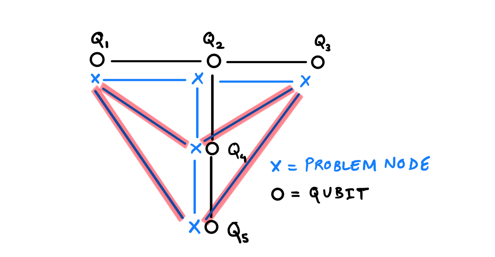
QAOA circuits are a type of variational circuits with alternating layers of parametrized cost and mixer operations. Typically, the cost layer contains entangling gates between pairs of qubits. In most cases, these entangling operations may act between qubits that are not physically connected on the hardware. In such cases, the circuit compilation uses qubit routing as a solution to map these operations onto the limited connectivity offered by the Quantum Computer. The figure below, as an example, shows these gates marked in red that cannot be implemented due to the lack of an entangling channel between the qubits.
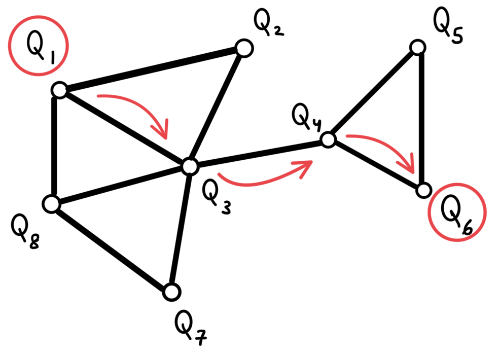
To circumvent the absence of connected edges between qubits, qubit routing solutions employ \(SWAP_{ij}\) gates, that swap the state of qubits \(i,j\) physically on the hardware. This allows the desired qubit state to travel along the chain of physically connected qubits as shown in the following figure.
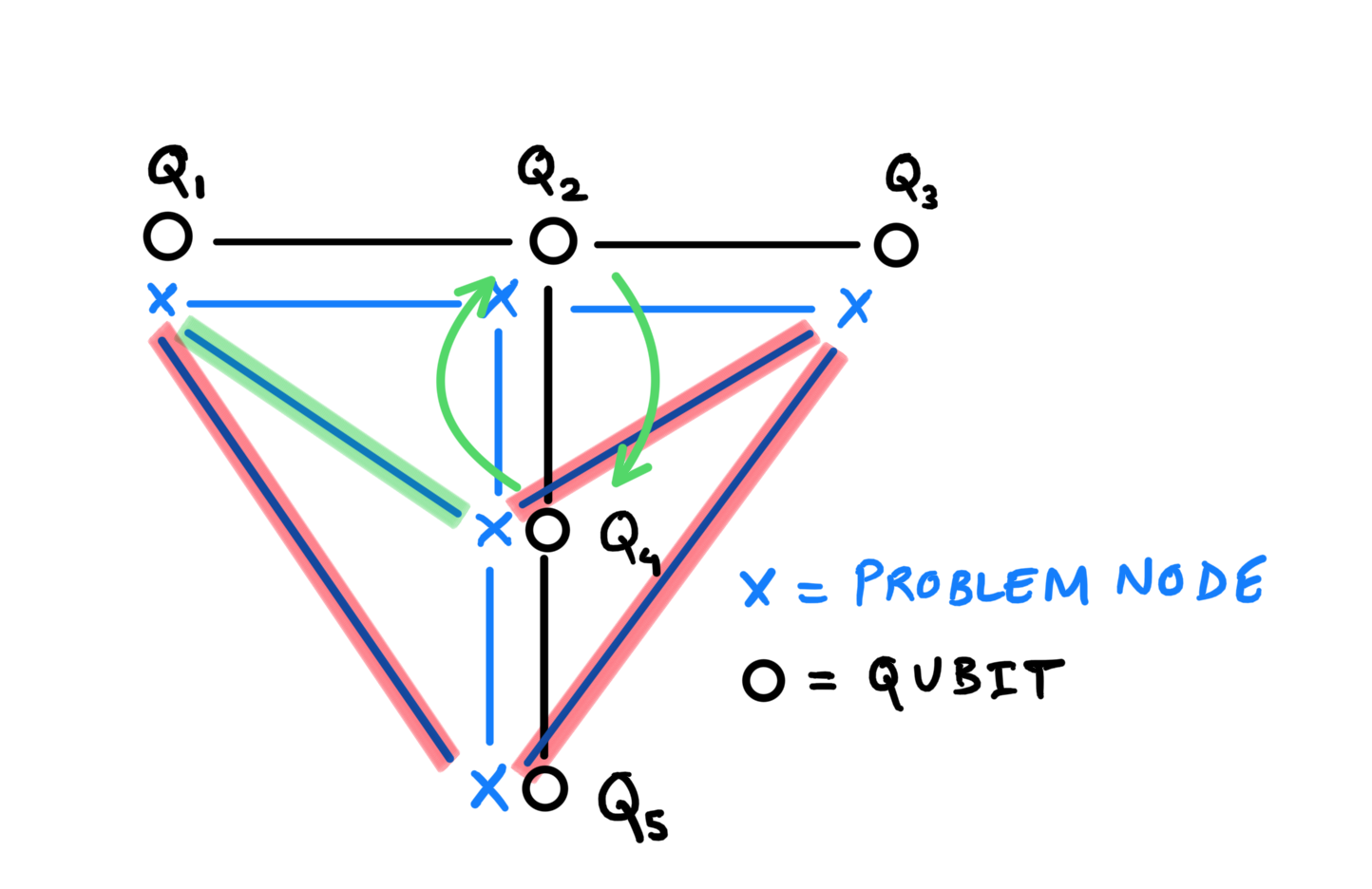
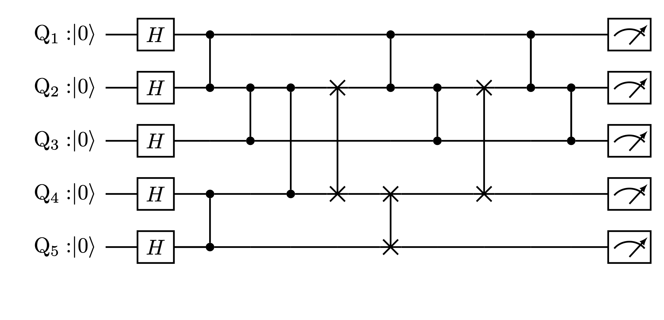
Such application of SWAPs can facilitate the swapping of positions of the two qubits \(Q_2, Q_4\) as shown in the figure below. This now allows us to implement the required entangling gates between qubits \(Q_1,Q_4\), and between \(Q_3,Q_4\). Similarly, the entangling gates with \(Q_5\) can be implemented by first swapping the qubits in the current position of \(Q_4\). The final equivalent circuit will resemble to that in the following figure.
Special properties of QAOA circuits
As mentioned earlier, QAOA circuits consists of alternating layers of a cost and a mixer layer.
For a standard QAOA, the mixer layer consists of single-qubit \(RX\) gates. Therefore, routing is only required for the cost layer, where each gate in the cost layer is either a parameterized \(RZZ(\gamma)\) or \(RZ(\gamma)\). Since all gates within the cost layer commute with each other, our qubit routing solution can take advantage of this by reordering the gates for better SWAP sequences and lower circuit depth.
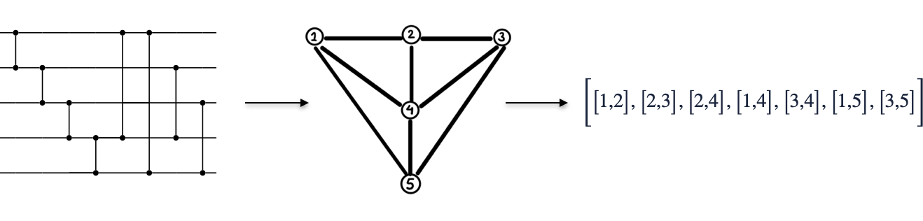
Before, we start desigining a solution to implement qubit routing, note that we can also omit the single qubit \(RZ(\gamma)\) gates as they do not influence the routing solution. Moreover, as the remaining gates in the sub-circuit to SWAP are all \(RZZ(\gamma)\), we can reformulate the set of gates as a graph. One can simlpify even further to represent the same as a list of edges of the graph. This transformation is also depicted in the figures below.
Qubit Routing solutions in OpenQAOA
Implemeting your own custom qubit routing solution in OpenQAOA is really simple! Owing to the simplifications in the input circuit from QAOA (as discussed above), it can be represented as a list of edges.
The custom routing solution is then expected to accept the circuit (as a list of edges) and the openqaoa.Device object as input to produce a routed circuit.
The custom routing function is also expected to output other relevant information regarding the process. These are described below:
- initial_mapping (
List[int]): This list reports selected qubits on the QPU that the algorithm will be executed on. For example, it is assumed that for aninitial_mapping = [b,a,d,c,f,e], the logical to physical qubit mapping is defined as{0:b,1:a,2:d,3:c,4:f,5:e} - routed_gates (
List[List[int]]): The routed gate set is output in the same format as the input gate set. This list contains pairs of qubits where a two-qubit gates is applied. Each of these pair is either anRZZor aSWAPgate. Each pair is defined using logical qubits, i.e. qubits numbered from[0, 1, 2, ... n-1] - swap_mask (
List[bool]): This output tags each qubit pair (gate) in therouted_gateslist above as either aSWAPgate if the entry isTrueor anRZZgate if the entry isFalse. - final_qubit_mapping (
List[int]): This list reports the final order of the shuffled qubits after the application ofSWAPs. The list must be labelled with qubit indices from0ton-1
In order to define such a routing function, one can imagine the following template:
def my_custom_routing_function(
    device: DeviceBase,
    circuit_to_route: List[List[int]]
):
    """
    A python implementation of qubit routing for a QAOA circuit cost layer

    Parameters
    ----------
    device: DeviceBase
        OpenQAOA device to run the circuit on
    circuit_to_route: List[List[int]]
        The cost layer of QAOA represented as a list of
        edges to be routed

    Returns
    -------
    initial_mapping: List[int]
        The qubit labels of selected qubits to run the circuit
    routed_gates: List[List[int]]
        The routed cost layer of the QAOA circuit
    swap_mask: List[bool]
        Label for each gate in the routed_gates list
        True if its a SWAP, False otherwise
    final_qubit_mapping: List[int]
        Qubit order post SWAP application
    """

    #my custom routing function
    return(
        initial_mapping,
        routed_gates,
        swap_mask,
        final_qubit_mapping
    )
Testing your solution with OpenQAOA
To begin testing your routing solution, we can use OpenQAOA workflows. It is quite easy to plug-in your routing solution in the QAOA workflow for a problem of your choice. Presented below, is an example showing the usage of qubit routing within OpenQAOA for an IBMQ quantum computer.
from openqaoa import QAOA
from openqaoa.problem import MaximumCut
from openqaoa.backends import create_device

#define a networkx graph for which you want to solve Maxcut
maxcut = MaximumCut(my_problem_graph).qubo()

#define the Quantum Computer to use for running the QAOA

IBMQ.load_account() #load your IBMQ api_token
credentials = {
    hub:'ibmq',
    group:'open',
    project:'main'
}
device = create_device(location='ibmq', name='ibmq_xyz', **credentials)

#create QAOA workflow and optionally update the properties
q = QAOA()
q.set_device(device)

#compile the circuit
q.compile(problem=maxcut, routing_function = my_custom_routing_function)

#run the optimization loop
q.optimize()
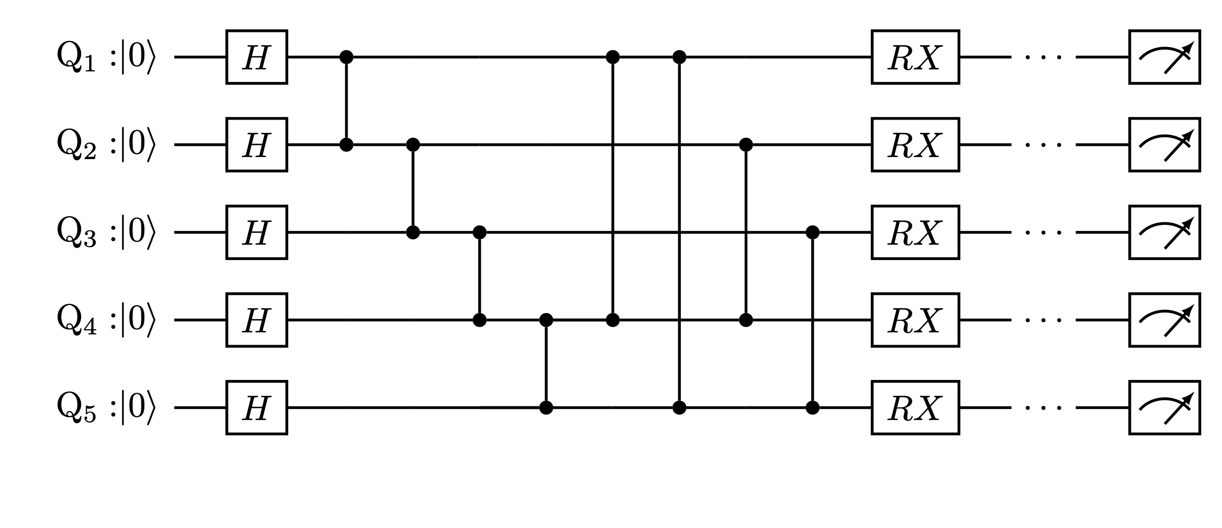
Additionally, OpenQAOA also lets you obtain the routed circuit by simply calling the parametric_circuit or qaoa_circuit on the backend object after compilation. For IBMQ devices, qiskit circuit is returned, and therefore, can be visualized by calling the .draw() method on the compiled circuit. For instance,
Moreover, one can tests their routing solutions on IBMQ emulators before targeting actual Quantum Computers by simply creating an emulator based on the real device. In OpenQAOA, as follows:
With simply this change, the problem now runs locally on your computer on a simulator modelling theibmq_xyz device.